
CAPACITOR
- Theoretical Analysis
- What is a capacitor and what is capacitance
A capacitor is an electric device which has two electrical conductors (plate) separated by dielectric material or air. The conductor can be films of metal, aluminium foil etc. and the dielectric can be glass, ceramic, paper etc.. The non-conducting dielectric acts to increase the capacitor's charge capacity.
If is supplies a constant voltage, an electric field develops across the dielectric, causing a positive charge to collect on one plate and negative charge to collect on the other plate. The process is called charge. To an ideal capacitor the electrostatic field can be exist forever, if is not an external cause change to that situation. In that case we say that the capacitor is charged and has the same voltage across the two plates with that was the source. So the capacitor stores energy in the form of an electrostatic field between the plates. Next to resistor, capacitor is the most common component.
The ability to store energy is called capacitance and the SI unit is called Farad (F). In practise the capacitance is between 1pF and 1mF.
Capacitor are used for blocking the dc current and allowing the AC. Also are used to smooth, rectified the output. They are used for telecommunication circuits eg radio receivers for tuning the frequency. The used as filters.
Capacitor are used for blocking the dc current and allowing the AC. Also are used to smooth, rectified the output. They are used for telecommunication circuits eg radio receivers for tuning the frequency. The used as filters.

- Capacitor in DC
Watch the video
So in DC is a current flow until the capacitor is charged.

The capacitance is given by: 
where Q is the charge on each conductor and V is the voltage across them.

the current and the voltage across the capacitor is given by

where To= R*C and is called time constant

From wikipedia

In the hydraulic analogy, a capacitor is analogous to a rubber membrane sealed inside a pipe. This animation illustrates a membrane being repeatedly stretched and un-stretched by the flow of water, which is analogous to a capacitor being repeatedly charged and discharged by the flow of charge.
In the hydraulic analogy, charge carriers flowing through a wire are analogous to water flowing through a pipe. A capacitor is like a rubber membrane sealed inside a pipe. Water molecules cannot pass through the membrane, but some water can move by stretching the membrane. The analogy clarifies a few aspects of capacitors:
- The current alters the charge on a capacitor, just as the flow of water changes the position of the membrane. More specifically, the effect of an electric current is to increase the charge of one plate of the capacitor, and decrease the charge of the other plate by an equal amount. This is just as when water flow moves the rubber membrane, it increases the amount of water on one side of the membrane, and decreases the amount of water on the other side.
- The more a capacitor is charged, the larger its voltage drop; i.e., the more it "pushes back" against the charging current. This is analogous to the fact that the more a membrane is stretched, the more it pushes back on the water.
- Charge can flow "through" a capacitor even though no individual electron can get from one side to the other. This is analogous to the fact that water can flow through the pipe even though no water molecule can pass through the rubber membrane. Of course, the flow cannot continue in the same direction forever; the capacitor will experience dielectric breakdown, and analogously the membrane will eventually break.
- The capacitance describes how much charge can be stored on one plate of a capacitor for a given "push" (voltage drop). A very stretchy, flexible membrane corresponds to a higher capacitance than a stiff membrane.
- A charged-up capacitor is storing potential energy, analogously to a stretched membrane.
- Capacitor in parallel and seris
- Parallel
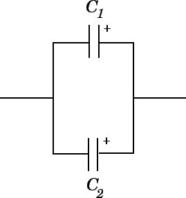
The potential difference across the two capacitors is the same. The total current is divided, some flowing into C1 and some flowing into C2. Hence Q=(I*t).
Qt=Q1+Q2
Qt=Q1+Q2
but Q=CV
so CV=C1V*C2V (/V)
C=C1+Q2
n-parallel connected capacitors

- Series
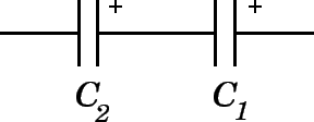
V=V1+V2
but V=Q/C
so
Q/C=Q/C1+Q/C2 (devide by V)
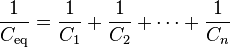
1/C=1/C1+1/C2
n-series connected capacitors
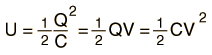
- Energy stored in capacitor
- Capacitor in AC
In AC the capacitor change behaviour. The current leads the voltage.I think with this video will understand better. As you know every subject has inertia, so the same happen with the capacitor in AC. Each change in polarity of the AC tends to disturb the equilibrium of capacitor where reached in the previous loading and change the polarity.The capacitor blocks the passage of the current with the reverse polarity.This reaction of the capacitor macroscopically appears as resistance to passage of the current. This resistance is called reactance.
So in AC circuit, the capacitor is charged and discharged according to the direction of the current and produce a impedance which depends on the capacity and the frequency of the AC.
So in AC circuit, the capacitor is charged and discharged according to the direction of the current and produce a impedance which depends on the capacity and the frequency of the AC.

At 0 degrees the rate of the voltage is positive and the current is at maximum point. When the voltage reaches the max point the current goes to 0 at 90 degrees. This happens because for an instant time is not any change of the voltage, so it is not any current flow. When the voltage goes to 180 degrees, the slope of voltage is negative and the capacitor is discharging in the negative direction. At 270 degrees the voltage is in maximum negative point so is not any current flow. As we can see the current leads the voltage.
- Capacity Reactance
Capacity reactance is opposite of current flow in AC. Reactance is measured in Ohms and it is frequency-depended.
The Capacity Reactance is given by:


Δεν υπάρχουν σχόλια:
Δημοσίευση σχολίου